Keyboard
The Pinebook Pro is available in two keyboard configurations: ISO and ANSI. Both the keyboard and touchpad in the Pinebook Pro use the USB 2.0 protocol and show up as such in xinput. The keyboard features function (Fn) keys in the F-key row, which include display brightness controls, sound volume, touchpad lock, and other functionality. There is also a custom PINE64 logo key that functions as Menu/Super key. It has also a secondary functionality for setting the privacy switches.
The keyboard firmware binary can be flashed from userspace using the provided open source utility.
| DO NOT update the keyboard firmware before checking which keyboard IC your Pinebook Pro has. Some Pinebook Pro were delivered with a SH61F83 instead of a SH68F83. The SH61F83 can only be written 8 times, this will render the keyboard and touchpad unusable if this limit is reached when step 1 is flashed, see the Reddit SH61F83 thread. The keyboard IC corresponds to U23 on the top layer silkscreen of the main board. It is located under the keyboard flat flexible cable. |
Documentation for the keyboard can be found in Datasheets for Components and Peripherals and details regarding the assembly can be found under Keyboard assembly.
Typing special characters
The UK ISO Layout does not have dedicated keys for characters like the German umlauts (Ä, Ö, Ü, etc). Certain characters can still be generated by means of either key combinations or key sequences.
Character | Key combination/sequence |
Ä, Ö, Ü, ä, ö, ü | [AltGr]+'[' followed by [A], [O], [U], [a], [o] or [u] |
µ | [AltGr]+[m] |
Ø, ø | [O], [AltGr][o] |
@ | [AltGr]+[q] (as on the German layout) |
ß | [AltGr]+[s] |
§ | [AltGr]+[S] |
° | [AltGr]+[)] |
Privacy Switches
There are three privacy switches mapped to the F10, F11 and F12 keys on the Pinebook Pro keyboard. They de/activate the following:
+ Privacy switch function and description | Combination | Effect | Description | Notes |
scope=row | PINE64 logo key+F10 | Microphone Privacy switch | CAPs lock LED blinks. 2 blinks = enabled, 3 blinks = disabled | scope=row |
PINE64 logo key+F11 | WiFi Privacy switch | NUM lock LED blinks. 2 blinks = WiFi enabled / privacy switch disabled, 3 blinks = WiFi disabled / privacy switch enabled. | Re-enabling requires reboot (or a [//forum.pine64.org/showthread.php?tid=8313&pid=52645#pid52645 command line hack to bind/unbind]). | scope=row |
(Press the PINE64 logo key plus F10/F11/F12) for 3 seconds)
The keyboard operates on firmware independent of the operating system. It detects if one of the F10, F11 or F12 keys is pressed in combination with the Pine key for 3 seconds. Doing so disables power to the appropriate peripheral, thereby disabling it. This has the same effect as cutting off the power to each peripheral with a physical switch. This implementation is very secure, since the firmware that determines whether a peripheral gets power is not part of the Pinebook Pro’s operating system. So the power state value for each peripheral cannot be overridden or accessed from the operating system. The power state setting for each peripheral is stored across reboots inside the keyboard’s firmware flash memory.
Basic summary of replacing keyboard
This guide is very basic and should be fleshed out with (better) pictures. There just isn’t a list of steps anywhere else yet.
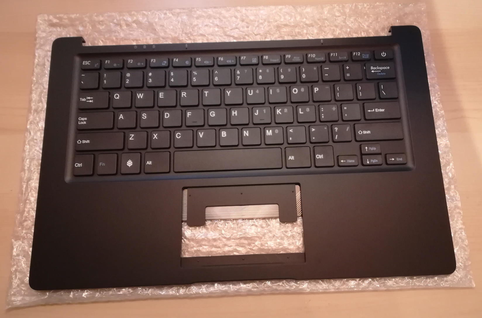
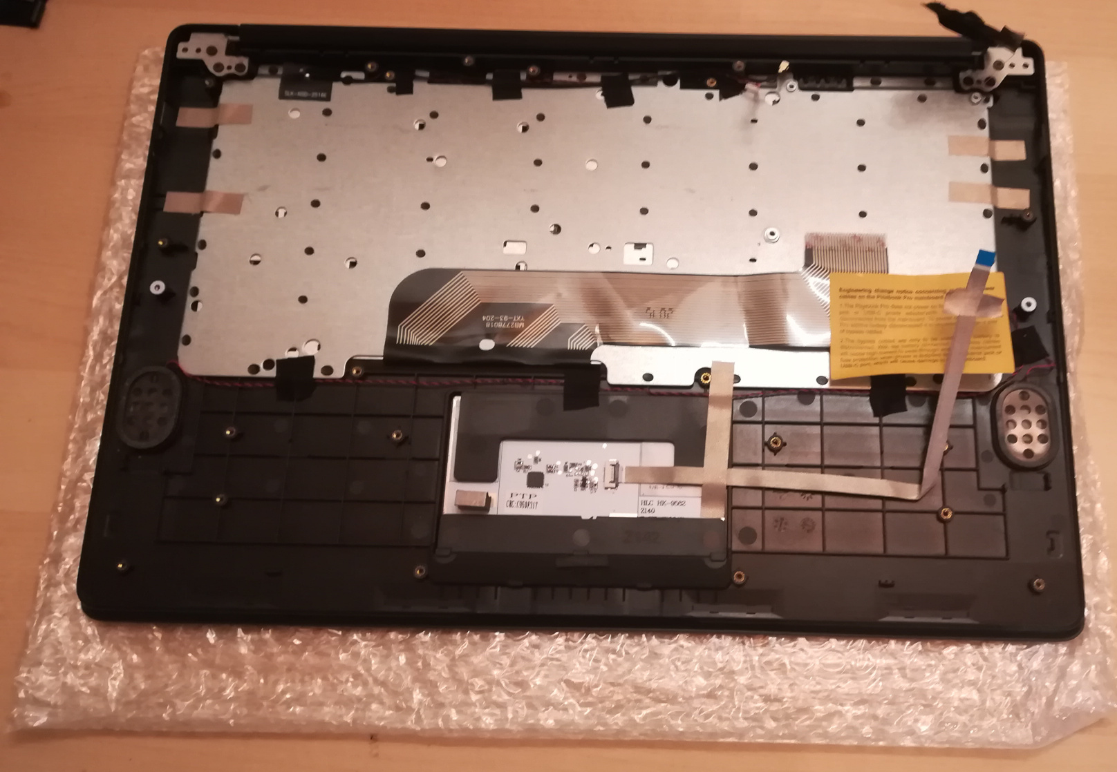
Here’s what the replacement keyboard looks like:
Step 0: If changing from ISO keyboard to ANSI keyboard, or vice versa, be sure to have a system capable of running the firmware updater that you can access either remotely or with a USB keyboard beyond the internal keyboard, as the firmware for each is very different and keys won’t work correctly. See https://forum.pine64.org/showthread.php?tid=8407 (and for NetBSD, https://forum.pine64.org/showthread.php?tid=8716).
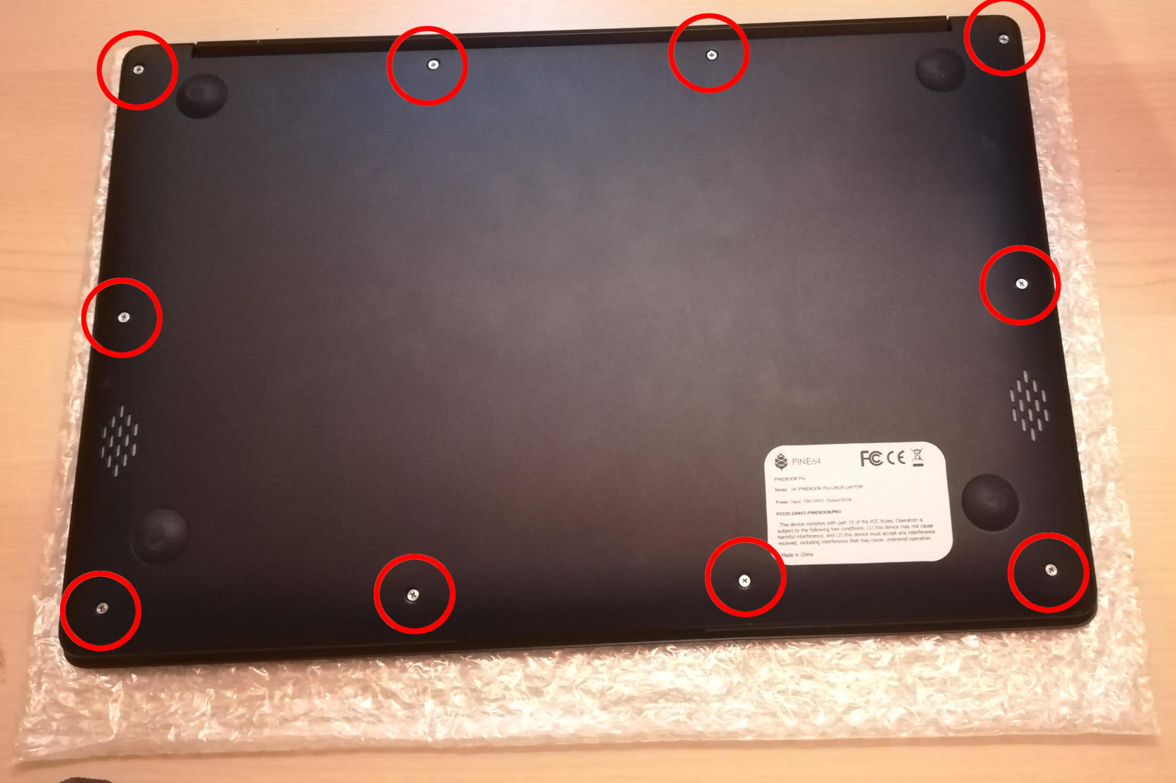
Step 1: The remove back back panel.
There are 10 screws on the back that must be removed, and the back panel detached. I recommend using a PH0 bit. The speakers may remain attached via glue to the case and should be carefully pried off. When this is done, taking photos of how everything looks now can help put it all back together later.
Step 2: Places to unscrew.
There are 3 items screwed into the keyboard frame that must be removed. There are 2 large screws for daughter board, 3 large screws and 1 small screw for mainboard, and 4 small screws for battery. Be sure to not lose them. I recommend a PH00 bit for the large screws on the daughter and main boards and a PH1 bit for the small screws on the battery and mainboard.
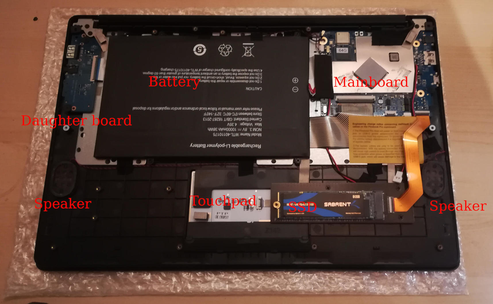
Step 3: Remove the battery.
Once the battery screws are removed, it should be unplugged from the mainboard and removed. Note that there are two unconnected cables lying around, that should remain unconnected. They are used when the battery is disconnected entirely.

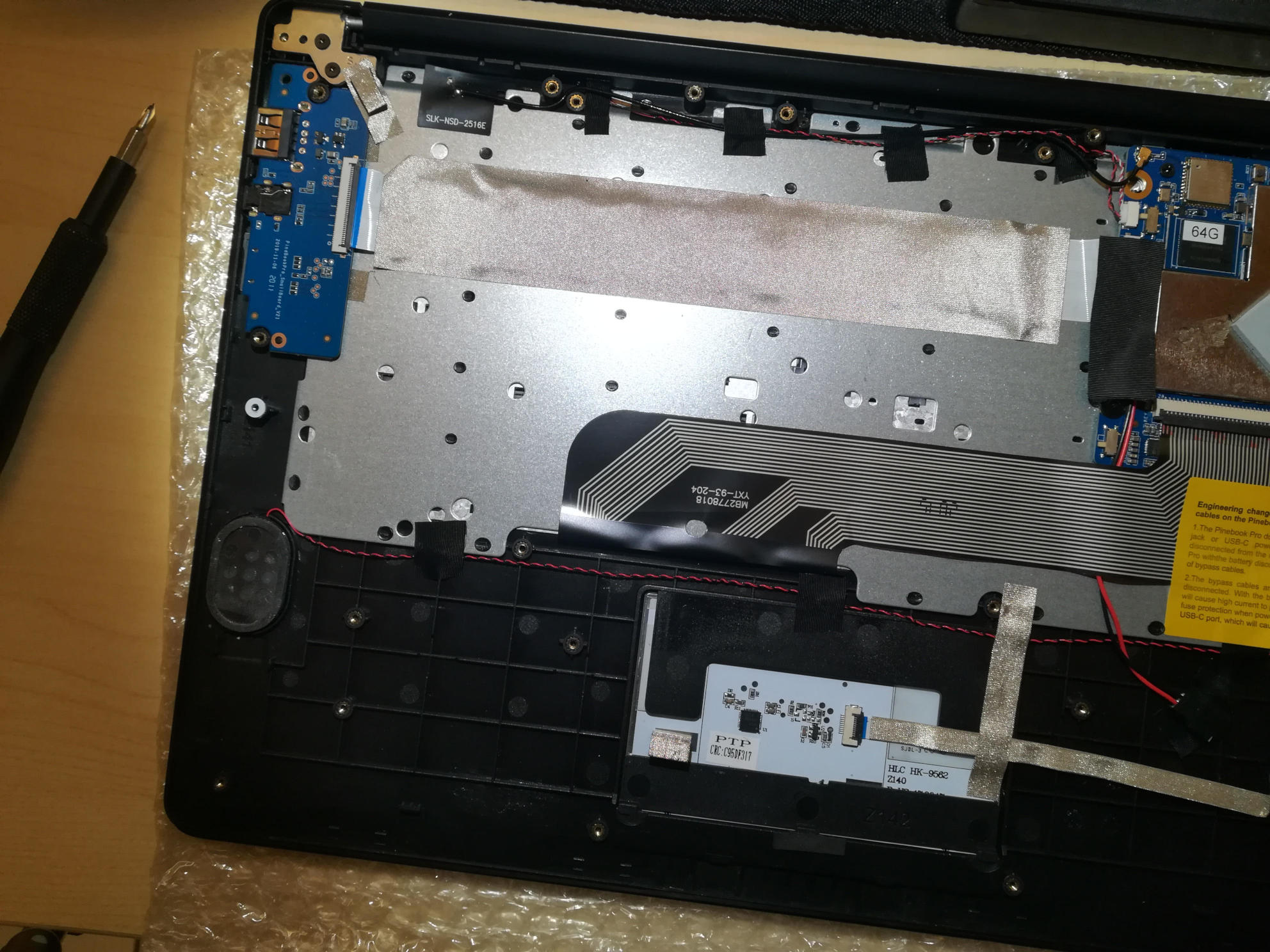
Step 4: Unplug the ribbon cables.
| you should remove the M.2 adapter board now if you have one installed. See elsewhere in the documentation for instructions on how to install/remove that piece. |
There are several ribbon cables. To remove, flip up the tab and gentle pull the ribbon out.
One cable runs from the mainboard to the daughterboard underneath the battery. Detach from both ends. With the battery removed, detach from keyboard shell, and set aside for the new keyboard shell.
One cable runs between the touchpad and the mainboard. Detach from both ends, and also set aside.
One cable runs between the keyboard and the mainboard. This one remains attached to the keyboard and only needs to be detached from the mainboard.
One cable from the LCD attaches near the lid hinge. It should be just unplugged.
Step 5: Detach microphone, speakers, and antenna.

The speakers, microphone, and antenna don’t have to be detached from the mainboard, but they need to be detached from the keyboard shell. The microphones are held in place by tape, and the speakers have sticky sides. The speakers are found obviously, but the microphones (two of) can be found between the battery and the hinge area. Each microphone can be carefully pulled/wedged out of its position by a small screwdriver or pick. The antenna, similar to the microphones, is found near the hinge area and to the top left of the battery.
Step 6: Remove mainboard and daughterboard.
At this point, the mainboard and daughterboards should be removed. When unscrewed (see Step 2) they should pull out fairly easily. Put them aside (including microphones and speakers if left attached.)
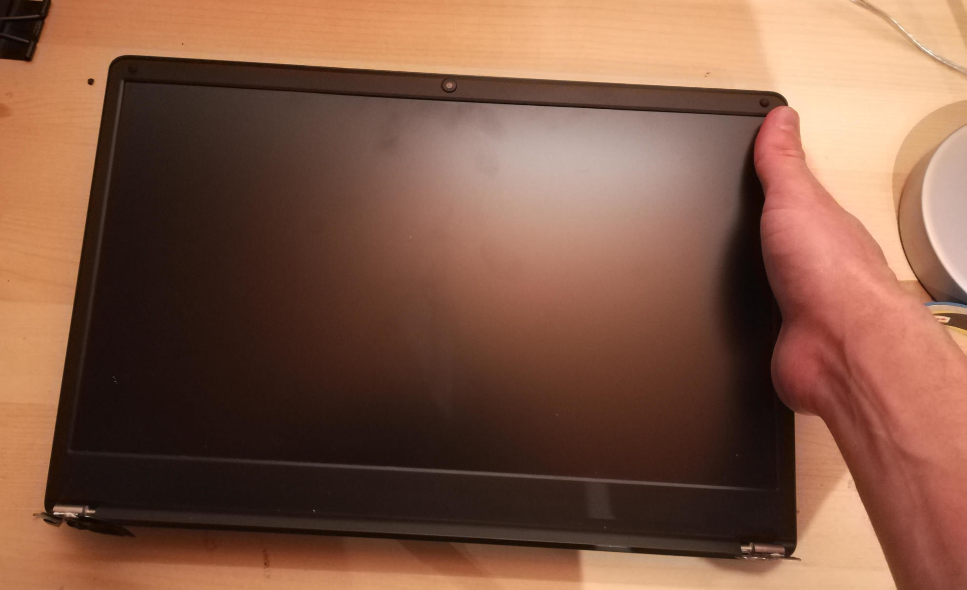
Step 7: Detach the LCD panel.
Step 2 didn’t tell you, there are 6 more screws to remove here, 3 for each of the hinges. I recommend a PH1 bit for these screws. Unscrew these and the LCD panel will be able to be removed. You may have to jiggle or move the hinges for this. When detached, be sure to place the LCD panel such that the display is protected.

Step 8: Try not to break your touchpad
NOTE This section really feels like you’re going to break something.
The touchpad is glued to the keyboard shell and it’s glued well. There are two places it is glued to. If you can, only the middle must be force-detached. You will think you’re going to break it. Gently apply increasing force until the glue begins to detach (you will hear a crackle as it comes off), and continue very slowly until the whole thing is detached. This may take minutes due to that feeling you’re going to break it.
I found it helpful to lift the top left plastic bit on the keyboard to unstick that portion of the touchpad, then push on the top left portion of the touchpad to unstick the rest of the touchpad.


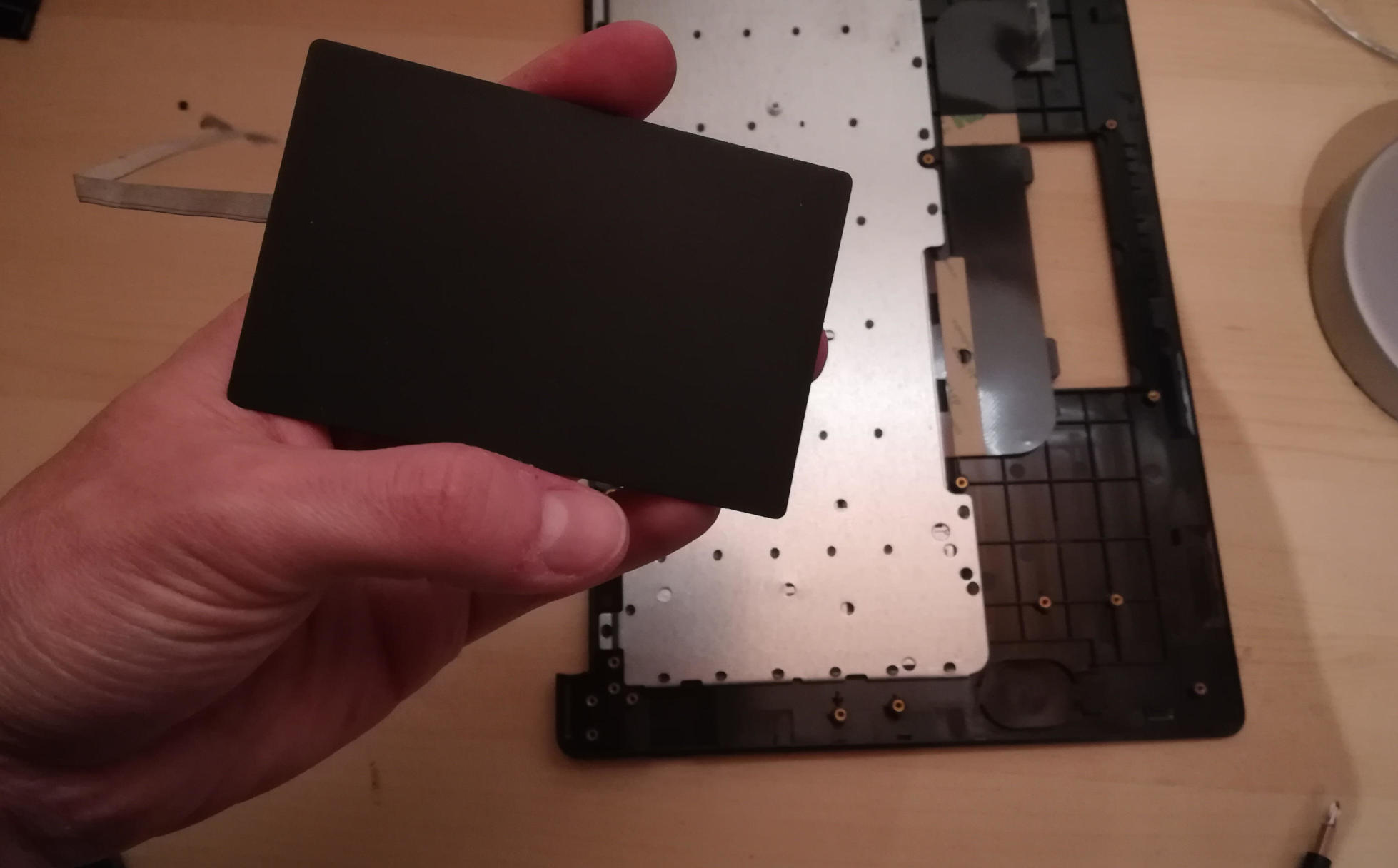
Step 9: Over the hill, touchpad goes into new shell.
In the new keyboard shell put the touchpad back where it was, hopefully the glue will remain sufficiently attached. If there is a glue issue, this guide unfortunately has no advice currently.
Step 10: Reattach the LCD panel.
The LCD panel should slot back into the keyboard frame, the same way it came out. If the hinges were moved, they should be very gently closed such that the LCD panel and keyboard closed like normal for the remaining steps.
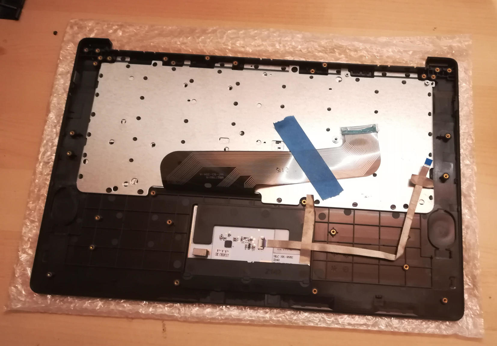
Step 11: Tape it out.
Move any tape from the old keyboard shell to the new one. These items protect the mainboard and daughterboard, and keep various wires in their right place. Some are grey and some are black. For tape that holds the speakers, microhones, or their cables in place, do not reattach yet.
Step 12: Board install.
Install the mainboard, the daughtboard, and their connecting ribbon cable. Be sure to put the boards in place, 2 large flat screws for the daughterboard, 3 large flat screws and one small screw for the mainboard, before attempting to place the ribbon.
Step 13: Microphone, speaker, and antenna install.
Reattach the microphones, antenna, and speakers to their respective areas, making sure that both are properly oriented - the speaker "out" faces up, and the microphone cables as connected must face up (these are opposite directions.)
Step 14: Reattach other ribbon cables.
| this would be a good time to attach/install the M.2 adapter board if that is desired. See elsewhere in the documentation for those instructions. |
The LCD panel, keyboard and touchpad ribbon cables should be reattached. Make sure the flap is open, insert the ribbon into the slot (a portion of the cable will disappear), and push the flap down. The cable should not be easy to pull out.
Step 15: Reattach the battery, and final re-tape.
The battery should be installed with the 4 screws holding it in place, and the connector attached to the mainboard. Be sure to keep the two other cables remain unconnected. Ensure all wires and other tapes are held in place.
Step 16: Reattach the back panel.
Put the back panel back on, and reattach the 10 screws.
Step 17: If you changed from ISO to ANSI or from ANSI to ISO, you’ll need to update your firmware now. See the links in Step 0 above.