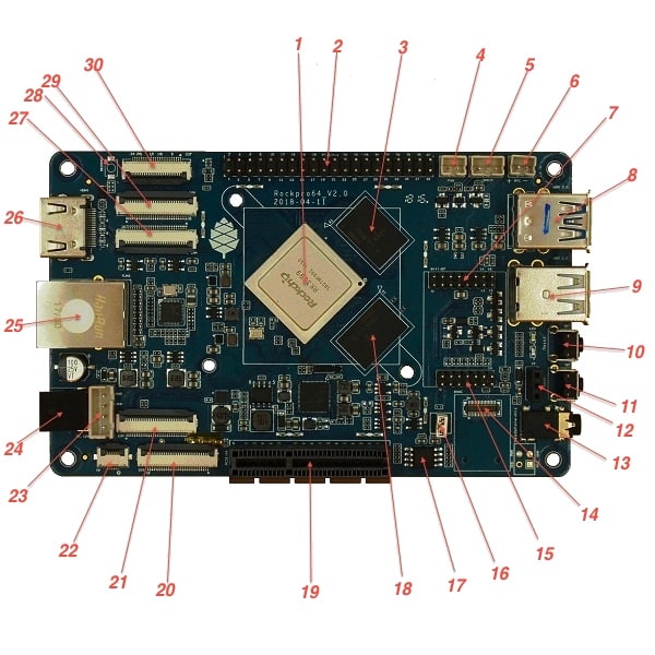
Layout
Main Chips
RK3399 system-on-chip (1)
LPDDR4 SDRAM 1 (18)
LPDDR4 SDRAM 2 (3)
SPI NOR flash memory (17)
RK808 power management (near 19)
RTL8211 ethernet transceiver (near 25)
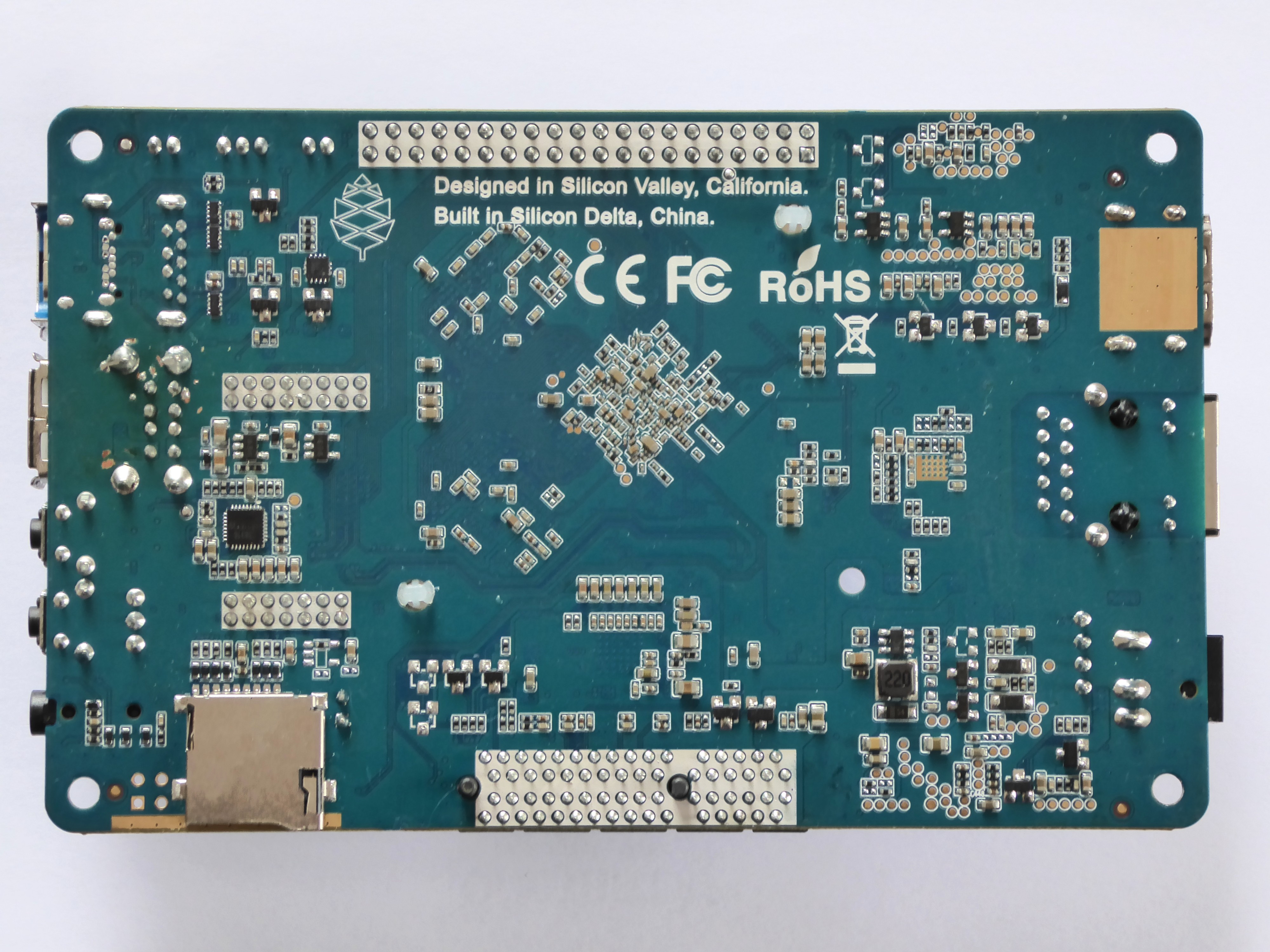
ES8316 Sound Codec (on rear of board)
The heatsink mounting holes around the RK3399 are 59 mm apart
Switches
The Power button (11, SW3): is the same as on your mobile phone - press and release after about 1 second to power on. Press and hold for about 3 seconds to power off.
The Reset button (10, SW901): performs a reset.
The Recover button (28, SW900): used to enter maskrom mode.
Connectors, Sockets and Headers
| Diagram | Schematic designator | Silkscreen label | Number of pins | Description |
|---|---|---|---|---|
2 | U39 | PI-2-bus | 40 | Pi-2 bus |
4 | J8 | +FAN- | 2 | PWM controlled fan header |
5 | J10 | SPDIF | 3 | SPDIF header |
6 | U6 | +RTC- | 2 | RTC battery backup header |
7 | U31 | Wifi-BT | 16 | SDIO WIFI/BT module-MIMO 2 |
8 | USB3 | 9 | USB-3 and USB Type C | |
9 | USB1 | 2×4 | Dual USB-2 | |
12 | IR1 | IR | 3 | infrared receiver socket |
13 | J16 | Headphone+mic | 4 | Headphone + mic 3.5mm jack |
- | CON16 | GND PWR RST GND | 4 | Power & reset, unpopulated header near Headphone jack |
14 | U29 | EMMC | 34 | eMMC connector (Note: Some datasheets indicate a low supported number of mating cycles.) |
14* | J13 | 13 | TF-card, a.k.a. microSD (* under 14 on the bottom side) | |
15 | U30 | 14 | SDIO WIFI/BT module-MIMO 1 | |
16 | SW4 | 2 | Jumper to Disable eMMC | |
19 | J15 | PCI | 64 | PCI-express X4 socket |
20 | J21 | DSI | 30 | DSI |
21 | J22 | EDP | 30 | LCD EDP |
22 | CON1 | TP | 6 | touch panel connector |
23 | CON15 | 4 | DC out for SATA disk cable (direct connect from DC-IN) | |
24 | J11 | DC-IN | 2 | Power input, positive tip; 12V/3A (minimum) recommended |
25 | U32 | 8 | 8P8C (often referred to as 'RJ45') | |
26 | J14 | 19 | HDMI | |
27 | J17 | MIPI CAM | 32 | MIPI-1 |
29 | J19 | MIPI CAM | 32 | MIPI-2 |
30 | J18 | CIF | 26 | CIF |
LEDs
A green LED next to the 12V input barrel connector will light as long as there is 12V applied to the connector. (Even if the RockPro64 is powered off.)
A white LED behind the reset button will light as long as the RockPro64 is running (it comes on a few seconds after power on, when control is passed to the operating system.)
A red LED behind the reset button is DIY - it is lit for example if the board is in OTG mode with an Ayufan image, or if an Android image is in standby mode.
Yellow and green LEDs on the LAN socket behave in a standard way.
Jumpers
They are used for boot device selection, as described in the following section.
Disable eMMC
There is an unlabelled (on the PCB silk-screen) 2-pin jumper (16) between the eMMC socket (14) and the SPI chip (17). It is designated as SW4 on the schematic diagram under "Board Information, Schematics and Certifications". The default condition is OPEN (no jumper). It is useful for controlling the boot as follows:
Default boot device (with no SPI software) is eMMC, then SDcard. If both the eMMC and the SDcard contain bootable images then the eMMC can be disabled by installing the jumper. This completely removes the eMMC from the resulting OS. If you wish the eMMC to be visible in the booted OS the jumper should be removed 2 seconds after applying power (and before the white LED comes on).
The possible combinations are summarised in the table below.
1 = present
0 = not present
| µSD | eMMC | SW4 | boot from |
|---|---|---|---|
0 | 0 | 0 | unsupported |
0 | 0 | 1 | unsupported |
0 | 1 | 0 | eMMC |
0 | 1 | 1 | unsupported |
1 | 0 | 0 | SDCard |
1 | 0 | 1 | SDCard |
1 | 1 | 0 | eMMC |
1 | 1 | 1 | SDCard |
Disable SPI (while booting)
There is a second possibility to jumper your ROCKPro64: If you mess-up your SPI and are unable to boot, jumpering pins 23 (CLK) and 25 pin (GND) on the PI-2-bus header will disable the SPI as a boot device. (This was taken from the IRC logs, 09 August 2018 @ 17:23) You have to remove the jumper 2 seconds after having started your RP64 (before the white LED turns ON) otherwise the SPI will be missing and you won’t be able to flash it. Ayufan images contain (at the moment) only one script for the SPI and the RP64, it’s "rockpro64_reset_spi_flash". Other SPI scripts are dedicated to the R64 (as it is written on the name) and it will mess-up your RP64 SPI if you use them.